The assignment consisted of planning an automated assembly system for a product known as ABB OT160.
This project was completed on the course Production Automation Planning at Tampere University. The product is a 3-pole, front operated, base mounted switch-disconnector, and its structure is composed mainly of plastic material with some metallic parts to provide its electrical functions.
The annual production volume desired for this product is circa 500 000 units and the production is set to operate five days a week in three shifts. Other ABB products, for example, robots, should be used in the automated product assembly system, if possible. Each production phase must be quality-checked automatically.
In phase one of the assignment, a design for assembly (DFA) analysis of the product was made. The analysis consisted of an assembly graph and a table identifying the different parts of the product, the problems in their assemblability and suggestions to improve them. Additionally, a calculation of the estimated assembly time was realized. As a result, an introduction to the new and re-designed case product was performed.
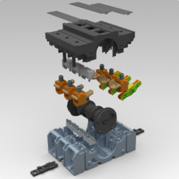
The next image shows the ABB OT160 model that our team worked with.
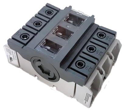
Our work began with analyzing the product ABB OT160 and focusing on the functions of the product parts. With DFA analysis we found that some of the parts were unnecessary to be separated so we were able to reduce the number of parts for the product. This was the first step in making a more straightforward assembly tasks. Some of the improvements didn’t reduce parts but nevertheless improved assemblability. Comparing the old and new design made an impact on the needed workforce to assembly the product by reducing almost 10 operators from the line.
The following images show one example of the analyses and changes that we performed: the original top lid is screwed to the bottom part. We changed the design of the parts where the top lid is fixed through snap fits. This solution allows to decrease the number of parts in the model and processes of assembly, which leads to a smaller work cycle in this specific work cell.

After we achieved the redesign model, we started developing a system that would be able to automatically assemble the product. This design process started with an analysis of the assembly process and how the new design was put together. Afterwards, we made a preliminary layout of the system and analyzed what was the needed cycle-time to meet the required capacity. After each cell was created, we simulated the results to verify our system met the requirements.
The following 2 images show the 2D layout (left image) and the 3D view (right image) of the production system.
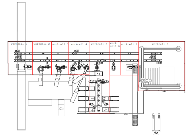
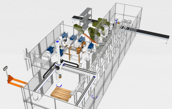
In each work cell created, an assembly process was idealized to be used with usual industrial tools such as robots, actuators, bowlers, conveyors. At the same time, we designed specific parts and grippers to make the assembly process possible.
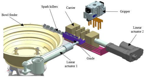
As an example of this, the following image shows how the spark killers parts are assembled in the bottom part of the model. It is necessary a bowl to feed the parts to be positioned in a specific position with linear actuators. After that, the robot with a design gripper ties the sparking killers and assembles them in the model.
The new automated line had a payback time of three years and we conclude that the new design and automated process is justified in an economic point of view.
You can read our detailed report here:


